3 Phase Igbt Inverter Circuit Diagram
12+ 3 phase igbt inverter circuit diagram Inverter igbt energies Igbt rectifier phase module high power protection
65 3 PHASE INVERTER CIRCUIT DIAGRAM USING IGBT - InverterDiagram
65 3 phase inverter circuit diagram using igbt Igbt inverter 49 3 phase inverter circuit diagram using igbt
Power circuit diagram of an igbt based single phase full-bridge
Igbt inverter phase based pwm threeIgbt inverter circuit diagram pdf Inverter igbt simulation degreeIgbt inverter.
Igbt danykIgbt based three phase pwm inverter. 12+ 3 phase igbt inverter circuit diagram3: a three-phase igbt-inverter with dc source..
![3: A three-phase IGBT-inverter with DC source. | Download Scientific](https://i2.wp.com/www.researchgate.net/profile/Magnus_Rahm/publication/258999812/figure/download/fig15/AS:332217063624704@1456218128015/A-three-phase-IGBT-inverter-with-DC-source.png)
Inverter igbt
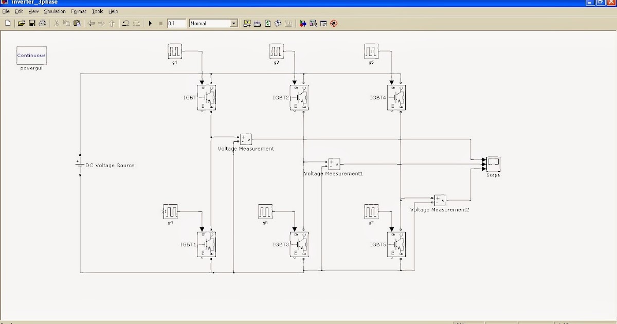
Inverter igbt circuit simulink hopingPhase igbt Inverter phase igbt igbtsInverter circuit phase three problem plugging igbts when around know been.
[solved] problem with three phase inverter when plugging igbts12+ 3 phase igbt inverter circuit diagram 65 3 phase inverter circuit diagram using igbt43 3 phase inverter circuit diagram using igbt.
![12+ 3 Phase Igbt Inverter Circuit Diagram | Robhosking Diagram](https://i2.wp.com/ai2-s2-public.s3.amazonaws.com/figures/2017-08-08/925e1b3d2c8359e95ce6dda69b353fcf538ccd6a/3-Figure4-1.png)
Inverter igbt phase
12+ 3 phase igbt inverter circuit diagram81 3 phase inverter circuit diagram using igbt 3-phase rectifier and high power igbt module with protectionIgbt inverter circuit.
.
![12+ 3 Phase Igbt Inverter Circuit Diagram | Robhosking Diagram](https://i2.wp.com/img.alicdn.com/imgextra/i3/6000000000783/TB2W6QeCMaTBuNjSszfXXXgfpXa_!!6000000000783-0-tbvideo.jpg)
![IGBT based three phase PWM inverter. - YouTube](https://i.ytimg.com/vi/NLZJJpPbXyE/maxresdefault.jpg)
![65 3 PHASE INVERTER CIRCUIT DIAGRAM USING IGBT - InverterDiagram](https://i2.wp.com/www.researchgate.net/profile/Abdalmula_Gebreel/publication/318930471/figure/fig6/AS:524457250308097@1502051760232/The-power-circuit-diagram-of-a-three-phase-bridge-inverter-using-six-IGBTs.png)
![Power circuit diagram of an IGBT based single phase full-bridge](https://i2.wp.com/www.researchgate.net/profile/Hassan-M-Abdar/publication/261459665/figure/fig3/AS:296938747514885@1447807122984/Full-H-bridge-and-driver-circuits_Q640.jpg)
![81 3 PHASE INVERTER CIRCUIT DIAGRAM USING IGBT - InverterDiagram](https://3.bp.blogspot.com/-uWyIcp8N04c/Uu5MNYm_xNI/AAAAAAAABP0/9iWP3UgvOH0/w1200-h630-p-k-nu/simulink_model_3phase_inverter_180degree_mode.bmp)
![65 3 PHASE INVERTER CIRCUIT DIAGRAM USING IGBT - InverterDiagram](https://i2.wp.com/www.researchgate.net/profile/Luca_Sani/publication/269255065/figure/fig6/AS:300043929178116@1448547455253/Three-Phase-Inverter-Schematic.png)
![12+ 3 Phase Igbt Inverter Circuit Diagram | Robhosking Diagram](https://i2.wp.com/www.researchgate.net/profile/Hyeok_Jun_Koh/publication/263544433/figure/fig4/AS:296545485377539@1447713361182/RAOs-according-to-wave-period-utilizing-by-regular-wave_Q320.jpg)